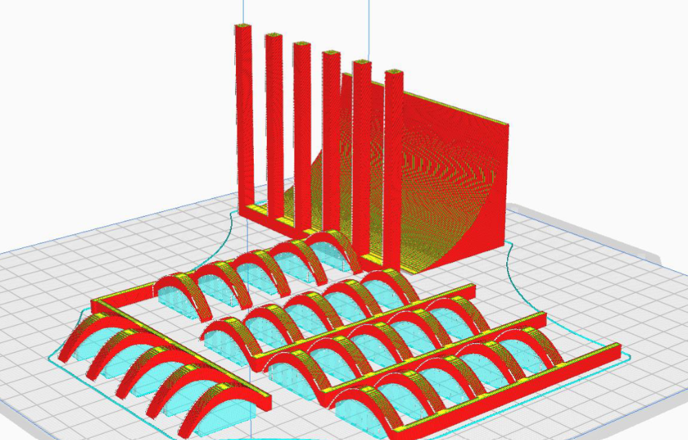
A 3D printing and designing role for a robot in the IEEE Hardware Competition involves creating custom components and structures using CAD (Computer-Aided Design) software to optimize the robot's functionality, weight, and durability. The designer collaborates with the team to conceptualize, prototype, and iterate on parts such as chassis, arms, grippers, or specialized attachments tailored to the competition's tasks. Once designed, the components are 3D printed using materials like PLA, ABS, or PETG, balancing strength and weight. The role requires a strong understanding of mechanical design, material properties, and 3D printing techniques to ensure the robot performs efficiently and reliably during the competition.
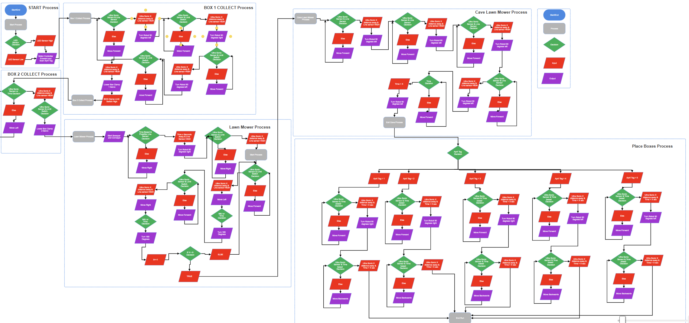
A flowchart for a robot's functions and tasks in the IEEE Hardware Competition would visually map out the decision-making process and actions the robot must perform. It typically starts with an initialization step (e.g., powering on and calibrating sensors), followed by a series of conditional checks and actions based on the competition's requirements. For example:
Start: Robot powers on and initializes systems.
Check Environment: Use sensors to detect objects, obstacles, or targets.
Decision Point: If an object is detected, proceed to pick it up; if not, continue searching.
Perform Task: Execute specific actions like grabbing, moving, or placing objects.
Check Completion: Determine if the task is complete or if additional steps are needed.
Loop or End: Repeat the process for multiple tasks or end the operation if all tasks are completed.
The flowchart uses shapes like ovals (start/end), rectangles (actions), diamonds (decisions), and arrows (flow direction) to clearly outline the robot's logic and ensure efficient task execution during the competition.
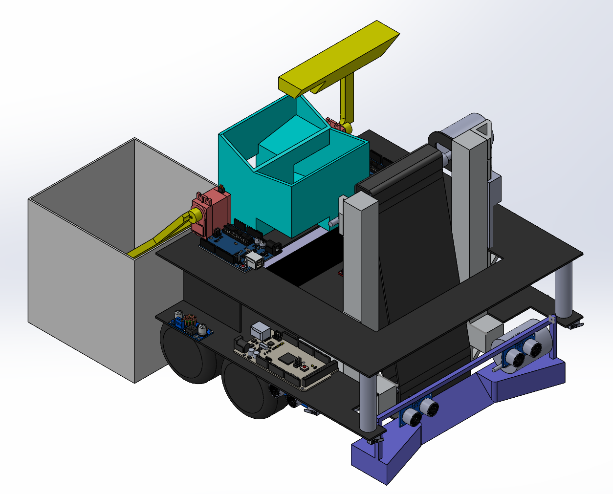
A complete CAD (Computer-Aided Design) model of the robot for the IEEE Hardware Competition is a detailed digital representation of the entire robot, encompassing all mechanical, structural, and functional components. It includes:
Chassis/Framework: The base structure that holds all components, designed for stability, weight efficiency, and ease of assembly.
Drive System: Wheels, tracks, or legs, along with motors and mounts, optimized for movement and maneuverability.
Manipulators/End-Effectors: Arms, grippers, or specialized tools designed to perform specific tasks like picking, placing, or interacting with objects.
Sensors and Mounts: Integration of sensors (e.g., cameras, IR, ultrasonic) for navigation, object detection, and task execution.
Power and Electronics: Placement of batteries, wiring, and control boards, ensuring accessibility and proper weight distribution.
Custom Components: 3D-printed or machined parts tailored to the competition's unique requirements, such as storage compartments or modular attachments.
The CAD model is created using software like SolidWorks, Fusion 360, or AutoCAD, and includes precise dimensions, tolerances, and assembly instructions. It serves as a blueprint for manufacturing, testing, and iterating the robot's design to ensure optimal performance in the competition.
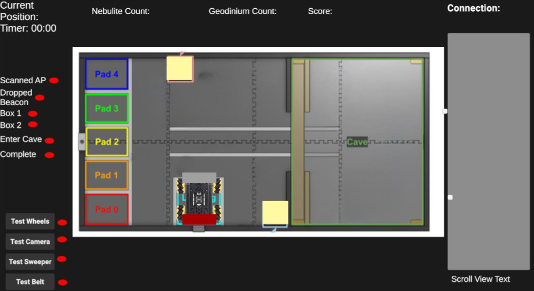
A debugger for the robot in the IEEE Hardware Competition is a tool or system designed to help the software team monitor, analyze, and troubleshoot the robot's behavior in real-time. It typically includes:
Real-Time Data Logging: Captures sensor data (e.g., distance, color, position), motor outputs, and decision-making states for review.
Error Detection: Identifies and flags anomalies, such as sensor malfunctions, incorrect motor movements, or logic errors in the code.
Visualization Tools: Displays data in graphs, charts, or live feeds (e.g., camera output, sensor readings) to provide a clear understanding of the robot's performance.
Step-by-Step Execution: Allows the team to pause, step through, and inspect the code's execution to pinpoint issues in the logic or control flow.
Simulation Integration: Tests the robot's software in a virtual environment before deploying it on the physical robot, reducing the risk of errors during competition.
User Interface: Provides an intuitive dashboard or console for the team to interact with the debugger, set breakpoints, and view system status.
The debugger is essential for ensuring the robot operates as intended, enabling the software team to quickly identify and resolve issues, optimize performance, and adapt to competition challenges. Tools like ROS (Robot Operating System), custom Python scripts, or integrated development environments (IDEs) with debugging features are commonly used.
Watch the full competition video to see the robot in action during the IEEE Hardware Competition. This video showcases the innovative design, dynamic performance, and real-time challenges faced by the team. Experience the excitement and engineering excellence firsthand!